Rewriting SPD
I recently pulled a few SDR (133 MHz) SO-DIMMs out of an old computer. They sat on my desk for a few days until I came up with a silly idea for something to do with them: rewrite the SPD information to make them only semi-functional- with incorrect timing information, the memory might work intermittently or not at all.
Background
Most reasonably modern memory modules have a small amount of onboard persistent memory to allow the host (eg your PC) to automatically configure it. This information is the Serial Presence Detect, or SPD, and it includes information on the type of memory, the timings it requires for correct operation, and some information about the manufacturer. (I’ve got a copy of the exact specification mirrored here: SPDSDRAM1.2a.) If I could rewrite the SPD on one of these DIMMs, I could find values that make it work intermittently or not at all, or even report a different size (by modifying the row and column address width parameters).
The SPD memory communicates with the host via SMBus, which is compatible with I2C for my purposes.
The job
| Pad | Signal |
| 140 | VSS (ground) |
| 141 | SDA (I2C data) |
| 142 | SCL (I2C clock) |
| 143 | VCC (+5 Volts) |
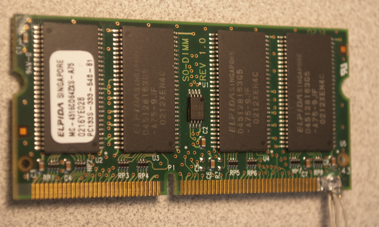
The hardest part of this quest was simply connecting wires to the DIMM in order to communicate with the SPD ROM. I gutted a PATA ribbon cable for its narrow-gauge wire and carefully soldered them onto the pads on the DIMM. Per information at pinouts.ru, I knew I needed four connections, given in the table to the right.
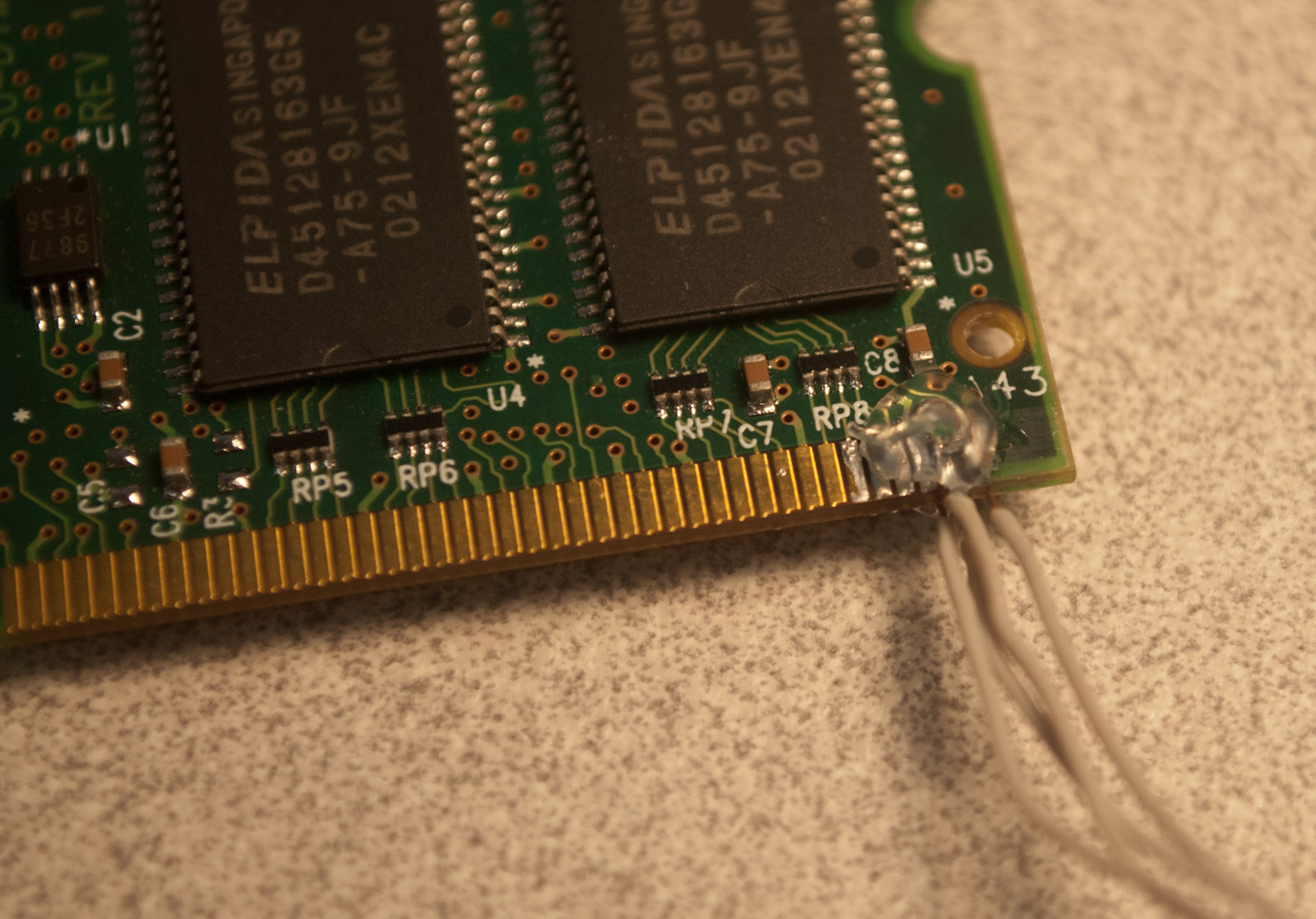
Note that the pads are labeled on this DIMM, with pad 1 on the left side, and 143 on the right (the label for 143 is visible in the above photo), so the visible side of the board in this photo contains all the odd-numbered pads. The opposite side of the board has the even-numbered ones, 2-144. With the tight-pitch soldering done, I put a few globs of hot glue on to keep the wires from coming off again.
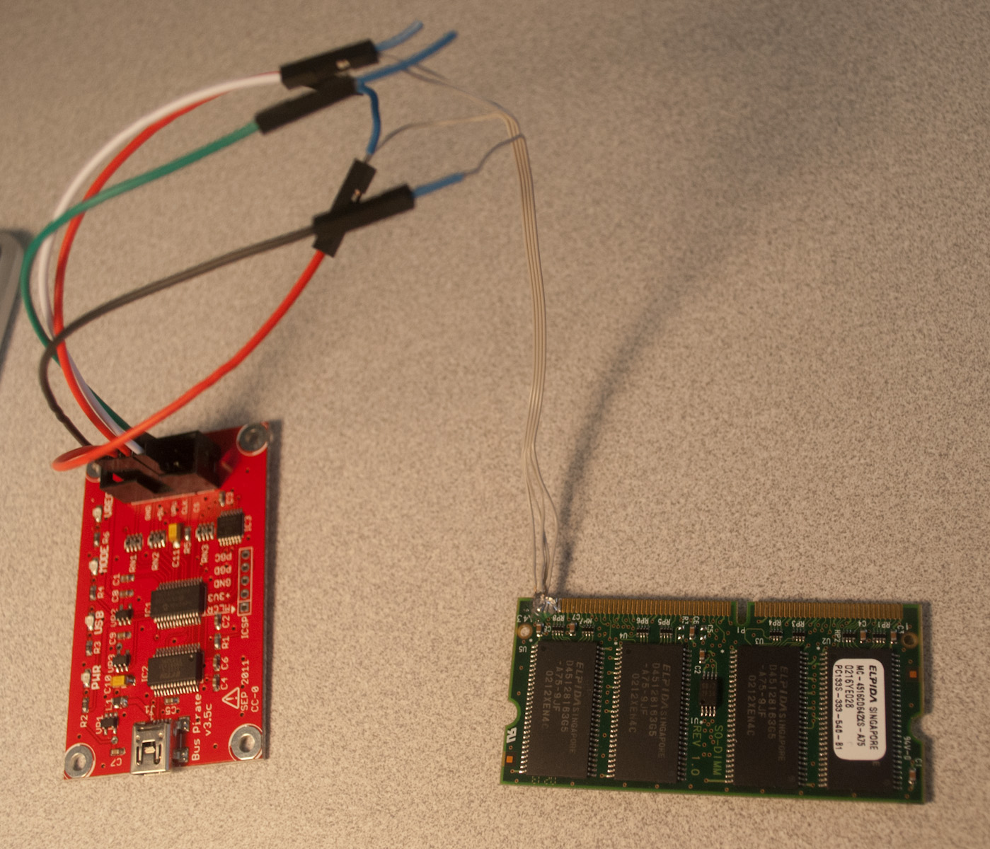
With good electrical connections to the I2C lines on the DIMM, it became a simple matter of powering it up and trying to communicate. I connected everything to my Bus Pirate and scanned for devices:
I2C>(1)
Searching 7bit I2C address space.
Found devices at:
0x60(0x30 W) 0xA0(0x50 W) 0xA1(0x50 R)
I2C>
The bus scan returns two devices, with addresses 0x30 (write-only) and 0x50 (read-write). The presence of a device with address 0x50 is expected, as SPD memories (per the specification) are always assigned addresses in the range 0x50-0x57. The low three bits of the address are set by the AS0, AS1 and AS2 connections on the DIMM, with the intention that the host assign different values to these lines for each DIMM slot it has. Since I left those unconnected, it is reasonable that they are all low, yielding an address of 0x50.
A device with address 0x30 is interesting, and indicates that this memory may be writable. As a first test, however, I read some data out to verify everything was working:
I2C>[0xa0 0][0xa1 rrr]
I2C START CONDITION
WRITE: 0xA0 ACK
WRITE: 0 ACK
I2C STOP CONDITION
I2C START CONDITION
WRITE: 0XA1 ACK
READ: 0x80 ACK
READ: 0x08 ACK
READ: 0x04 ACK
I write 0 to address 0xA0 to set the memory’s address pointer, and read out the first three bytes. The values (0x80 0x08 0x04) agree with what I expect, indicating the memory has 128 bytes written, is 256 bytes in total, and is type 4 (SDRAM).
Unfortunately, I could only read data out, not write anything, so the ultimate goal of this experiment was not reached. Attempts to write anywhere in the SPD regions were NACKed (the device returned failure):
I2C>[0xA0 0 0]
I2C START CONDITION
WRITE: 0xA0 ACK
WRITE: 0 ACK
WRITE: 0 NACK
I2C STOP CONDITION
I2C>[0x50 0 0]
I2C START CONDITION
WRITE: 0x50
WRITE: 0 ACK
WRITE: 0 NACK
I2C STOP CONDITION
In the above block, I attempted to write zero to the first byte in memory, which was NACKed. Since that failed, I tried the same commands on address 0x30, with the same effect.
With that, I admitted failure on the original goal of rewriting the SPD. A possible further attempt to at least program unusual values to a DIMM could involve replacing the EEPROM with a new one which I know is programmable. Suitable devices are plentiful- one possible part is Atmel’s AT24C02C, which is available in several packages (PDIP being most useful for silly hacks like this project, simply because it’s easy to work with), and costs only 30 cents per unit in small quantities.