Divergence Meter
This is a project to create a replica of the divergence meter that appears in the anime and visual novel Steins;Gate. Some other enterprising developers have built their own versions (including this impressively accurate one), and there is an official replica available.
Build Log
Notes as the project continues can be found under the divergence-meter tag on this site.
What it does
In the Steins;Gate universe, the divergence meter indicates how much the current world line diverges from the alpha world line. The interpretation of time travel used in this universe involves a person jumping between multiple world lines which are substantially parallel. The divergence meter, created by Okabe Rintaro in the future of the timelines depicted in the anime, allows one to keep track of how much the world may differ from what they would expect. This is only of particular use to Okabe, due to his ‘Reading Steiner’, which allows him to remember when he jumps between world lines.
Rather obviously, the actual divergence functionality makes no sense in a real-world replica, but it is still useful for theatrical effect, since half the fun of building a replica of anything is making it act similar to what it is based on. With an eight-digit display, an obvious option is to have it act as a clock, since eight digits is plenty to display the time of day, as well as the current date. With a programmable microcontroller and a back-channel to communicate with it, it should be possible to do just about anything I find might be useful, such as displaying environmental conditions.
Source
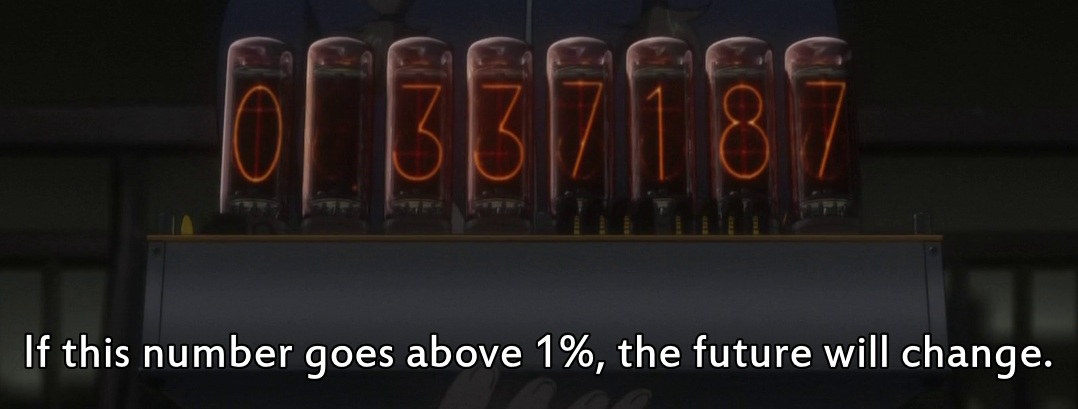
The above image illustrates the overall design of the divergence meter (framegrabs taken from episode [TO BE DETERMINED]). It’s an 8-digit Nixie tube display driven by unspecified electronics, in a case that appears to be some sort of riveted sheet metal. The tubes themselves appear to be IN-18 tubes of Soviet manufacture, and the topmost board contains a variety of exposed circuit elements. Considering that nixie tubes require a potential of around 200V to fire, that seems rather unsafe.
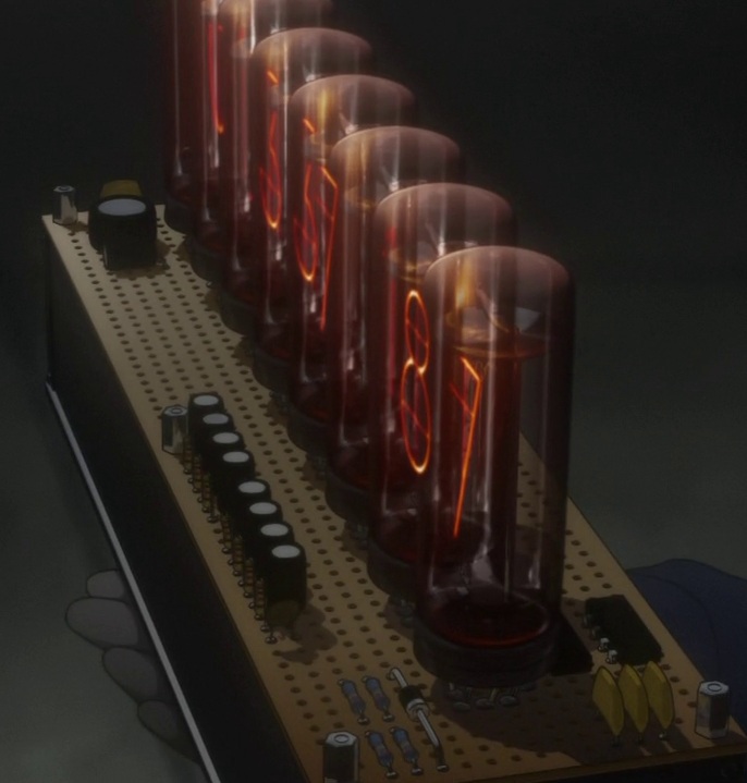
Examining it from another angle, we can see clearly that the exposed components are mostly capacitors and resistors. The eight resistor/capacitor pairs are probably related to driving the eight tubes (possibly power smoothing and current limiting), while the three capacitors on the left might be used for power filtering. A few more resistors and a diode round out the visible passive components.
There are a pair of 8-pin DIP ICs mounted behind the tubes which don’t make a lot of sense- a reasonable alternative might be a 74141 BCD cathode driver, which is a 16-pin DIP device capable of directly driving gas-discharge display elements (such as nixie tubes) with high voltages. Each 74141 is only capable of driving a single tube at a time, however, so the presence of only two chips is rather unusual.
The whole assembly is built on a piece of perfboard, and the hex standoffs on the edges indicate that there are additional layers of circuitry hidden inside the case. One must assume that power for the whole device is supplied by an internal battery since it is never depicted with an external power supply. Some consideration must be made for artistic license in creation of this design, so ultimately the only salient point of the design is that it hosts eight nixie tubes for display. When continuing with my construction, it may be reasonable to refer back to this more closely to have a convincing recreation. Until then, the visible components are unimportant.
My design
Having identified the important parts of the display (the IN-18 nixie tubes), it’s possible to begin coming up with a design. In the interest of keeping costs down, I opted to use the smaller IN-14 tubes instead. IN-18 Nixies are significantly harder to find and are rather expensive when they can be found ($50 per unit from TubeHobby), so I decided to use the cheaper and more plentiful IN-14 instead, of which I was able to get a batch of 9 used tubes from a seller on eBay for $35 with reasonably-priced international shipping.
In the interest of maintaining flexibility for later revisions to the design such as upgrading to IN-18 tubes or making aesthetic changes, I split the logic and display portions of the design between two circuit boards, to be joined with breakaway headers. Modularizing the design allows me freedom in upgrading either portion, and generally helps the development process. This modularity also follows the design of the meter as depicted in the anime, and includes mounting holes suitable for hex standoffs as depicted in the source material.
[Schematics to be included here once it has been built and tested]
Logic + Power Supply
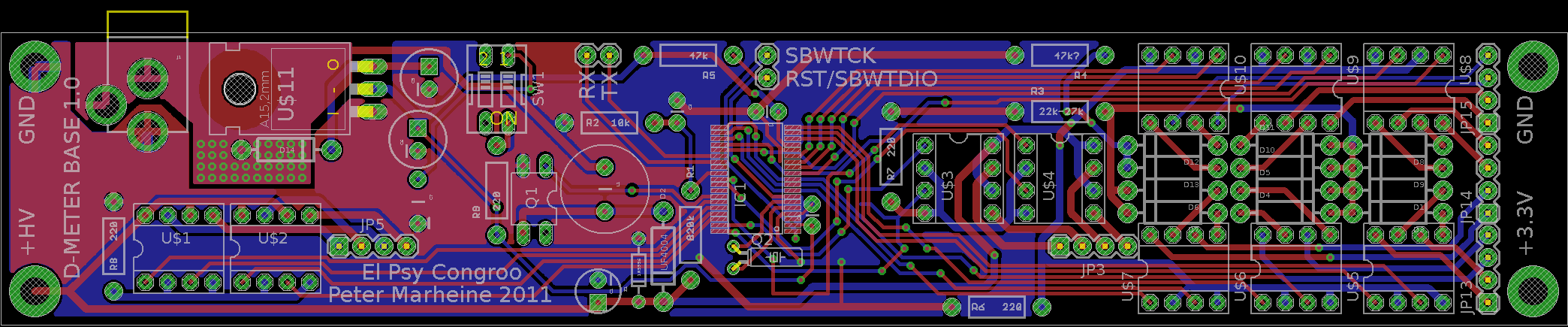
The central component of the logic and power supply board is a MSP430F2272 microcontroller. This is a low-power (as little as a few nanoamp current draw in sleep mode) 16-bit microcontroller with 32 kilobytes of program memory and 1 kilobyte of RAM, as well as a good selection of peripherals, including a digital oscillator, external clock source, several timers, and a 12-channel 10-bit resolution ADC.
The MSP430 microcontroller takes its power from a 3.3V power rail, which itself is driven from the system’s 9V main power supply. Backup power is supplied by a supercap on the 3.3V power rail, allowing the MSP430 to switch to a lower-power mode and continue operating when main power is lost. Continuing operation without main power is not an important feature, but it is convenient for the clock functionality if the clock need not be reset whenever it is unplugged. A DIP switch (chosen for the aesthetic appeal only) allows the backup power to be disconnected for testing. A back-channel for communication with the system is provided by breaking out a UART to an external header, and the lines for serial programming are broken out to another header for in-system programming without a bootloader.
The high-voltage supply for the nixie tubes is provided by a boost converter, which switches current across an inductor rapidly, utilizing the voltage spikes caused by rapid switching to create a smooth 190V supply rail. The PWM input to the boost converter is provided by the microcontroller, and feedback for calibration goes back to the MSP430’s analog inputs through a voltage divider. A 200V Zener diode ensures that the nixie supply rail cannot ever be driven higher than 200V, which is the maximum rated voltage for the tubes.
To reduce the component requirements, the nixie tubes themselves are multiplexed. A set of TLP627 2-channel optocouplers allows the MSP430 (which runs at 3.3V nominal) to safely switch the nixie supply onto the display cathodes, and another set of optocouplers connects the display anodes to ground with current-limiting, again controlled by the micro.
A preliminary bill of materials for the logic and power supply unit follows. Includes a brief description of each part, a quantity, and Mouser part numbers, with extended price as of November 2011.
| Part ID | Description | Mouser part no | Quantity | Ext. price |
| 200V Zener diode | 863-1N5956BG | 1 | $0.37 | |
| 32 kHz crystal | 732-C002RX32.76K-APB | 1 | $0.32 | |
| 3.3V LDO regulator | 511-LD1117V33 | 1 | $0.42 | |
| 2ch optocoupler | 757-TLP627-2FT | 10 | $9.60 | |
| DIP switch, 2 | 506-ADE0204 | 1 | $0.53 | |
| 220 Ohm | 4 | |||
| 47k Ohm | 2 | |||
| 27k Ohm | 1 | |||
| 10k Ohm | 1 | |||
| 820k Ohm | 1 | |||
| 200V MOSFET IRFD220 | 844-IRFD220PBF | 1 | $1.56 | |
| 680uH inductor | 580-13R684C | 1 | $0.60 | |
| 2mm barrel jack | 806-KLDX-0202-A-LT | 1 | $0.84 | |
| MSP430F2272 uC | 595-MSP430F2272IDAR | 1 | $5.41 | |
| 1A 400V diode | 625-1N4936-E3 | 13 | $0.65 | |
| 1A 400V schottky diode | 512-UF4004 | 1 | $0.15 | |
| .22F 5.5V supercap | 667-EEC-S0HD224V | 1 | $1.69 | |
| 470uF 16V cap | 647-UVR1C471MPD1TD | 1 | $0.09 | |
| 47uF 50V cap | 647-UVR1H470MED1TA | 1 | $0.06 | |
| .1uF decoupling cap | 581-SR215C104KAATR1 | 1 | $0.09 | |
| 250V 10uF cap | 647-UVY2E100MPD | 1 | $0.39 | |
| DIP-8 socket | 517-4808-3004-CP | 10 | $1.30 |
[More to come as the project continues]